| |
Complete front axle
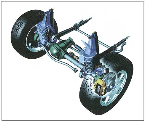
General
The front axle is designed as a rigid axle and fitted with two
coil springs. The characteristic curves of the coil springs are
linear. Gas pressure shock absorbers are installed
in parallel with the coil springs in order to absorb the
vibrations of the body and to assure contact with the road
surface. The front axle has a track of 1425 mm as standard. |
|
Axle
location
The front axle is located by two trailing arms which absorb the
starting-off and braking torques, and a track control arm (Panhard rod),
which absorbs the lateral forces. The trailing arms and the track
control arm are mounted at the frame and at the axle in
maintenance-free rubber elements. In addition, the front axle is
equipped with a stabilizer bar which minimizes the roll tendency
when cornering. |
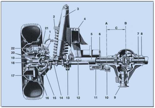
| Front axle design |
|
|
|
|
| 1 |
|
Brake line |
|
14 |
|
Track rod |
| 2 |
|
Coil spring |
|
15 |
|
Knuckle arm |
| 3 |
|
Gas pressure shock absorber |
|
16 |
|
Joint housing |
| 4 |
|
Frame |
|
17 |
|
Brake disc |
| 5 |
|
Axle tube |
|
18 |
|
Grease cap |
| 6 |
|
Left drive shaft |
|
19 |
|
Wheel hub |
| 7 |
|
Right drive shaft |
|
20 |
|
Tapered roller bearing |
| 8 |
|
Axle housing |
|
21 |
|
CV joint of drive shaft |
| 9 |
|
Drive flange |
|
22 |
|
Fixed caliper |
| 10 |
|
Differential lock indicator light
switch |
|
23 |
|
Steering knuckle pin |
| 11 |
|
Differential lock slave cylinder |
|
A |
|
Axle center |
| 12 |
|
Steering shock absorber |
|
B |
|
Axle housing center |
| 13 |
|
Trailing arm |
|
C |
|
190 mm |
| |
|
|
| The front axle consists
of an axle housing (8) with interference-fit axle tubes (5). The
tube ends are designed as a spherical shape for mounting the CV
joints of the drive shafts (21). |
|
The wheel bearing is
achieved by means of two tapered roller bearings (20)
The axle housing center (B) is offset 190 mm to the right compared
to the axle center (A). |
| |
|
|
 |
|
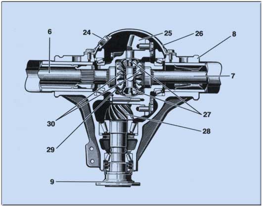
A bevel gear differential with
engageable differential lock is installed in the front axle. The
difference in speed when cornering is compensated by the four
differential bevel gears (27). These are mounted in the differential
housing (29). The input shaft bevel gears (30) are connected
torsionally- resistant to the drive shafts (6, 7) by means of a
gearing. installed in the front axle. The difference in speed when
cornering is compensated by the four differential bevel gears (27).
These are mounted in the differential housing (29). The input shaft
bevel gears (30) are connected torsionally- resistant to the drive
shafts (6, 7) by means of a gearing. |
| Differential design |
| 6 |
|
Left drive shaft |
|
26 |
|
Differential cover |
| 7 |
|
Right drive shaft |
|
27 |
|
Differential bevel gears |
| 8 |
|
Axle housing |
|
28 |
|
Drive pinion |
| 9 |
|
Drive flange |
|
29 |
|
Differential housing |
| 24 |
|
Oil filler plug |
|
30 |
|
Input shaft bevel gears |
| 25 |
|
Ring gear |
|
|
|
|
| |
|
|
 |
|
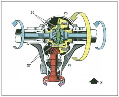
Function when driving straight
ahead
Both driven wheels rotate equally fast. Consequently, the two drive
shaft bevel gears (30) also rotate equally fast. The differential
bevel gears (27) do not rotate about their own axis, but
orbit as drivers together with the differential housing (29) which
is connected to the crown wheel (25). Consequently, the differential
bevel gears (27) transmit the speed coming from the engine in equal
portions to the drive shaft bevel gears (30).
x Direction of travel |
| |
|
|
 |
|
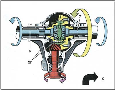
Function when cornering
(shown in right-hand curve)
When negotiating a right-hand curve the outer (left) driven wheel
must cover a longer distance than the inner (right) wheel.
Consequently, the left drive shaft (6) must rotate faster than the
right drive shaft (7). The difference in speed between the drive
shaft bevel gears (30), which are connected to the drive shafts (6,
7), is compensated by the differential bevel gears (27). In this
case, the differential bevel gears (27) rotate about their axis.
The inner driven wheel rotates more slowly by the amount by which
the outer driven wheel rotates faster, provided the power is
transmitted uniformly and both wheels have the same adhesion. In
this case the torque transmitted is equally high.
x Direction of travel |
|